PCB board troubleshooting is crucial for fixing electronic devices. Problems in PCBs can lead to device failure.
Understanding how to troubleshoot PCBs can save time and money. PCB boards are the heart of many electronic devices. They connect and support various components, ensuring everything works properly. Troubleshooting PCBs means identifying and fixing issues that disrupt these connections.
This process requires patience, keen observation, and some basic tools. Knowing common problems and their solutions can simplify troubleshooting. This guide will help you understand the steps to identify and fix PCB issues. By the end, you will be more confident in handling PCB problems. Let’s dive into the world of PCB troubleshooting and make those electronic devices work like new.
Introduction To Pcb Troubleshooting
Printed Circuit Boards (PCBs) are essential in modern electronics. They connect and support electronic components. Proper troubleshooting of PCBs can save time and resources. Understanding the basics is crucial for anyone working with electronics. In this section, we will discuss the importance of PCB maintenance and common PCB issues.
Importance Of Pcb Maintenance
Regular PCB maintenance ensures the longevity of electronic devices. It helps prevent unexpected failures. Well-maintained PCBs perform efficiently. They reduce the risk of costly repairs. Scheduled maintenance identifies potential issues early. This proactive approach saves time and money.
Common Pcb Issues
Several issues can affect PCB performance. One common problem is soldering defects. Poor solder joints can cause intermittent connections. This leads to device malfunction. Another issue is component failure. Components may fail due to overvoltage or overheating. Traces and pads can also get damaged. This can result from physical stress or environmental factors.
Short circuits are another frequent issue. They occur when unintended connections form. This can cause overheating and damage. Open circuits can also be problematic. They happen when connections break, disrupting the flow of electricity. Identifying and fixing these issues is crucial for optimal PCB performance.
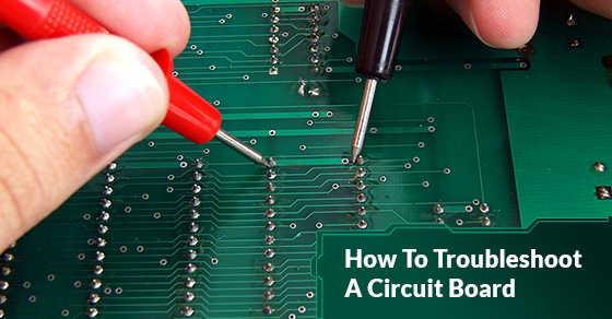
Credit: www.circuits-central.com
Essential Tools And Equipment
Troubleshooting PCB boards can be challenging but rewarding. The right tools and equipment make a significant difference. This section will cover the essential tools and equipment needed for effective PCB board troubleshooting.
Basic Tools
Basic tools are essential for any technician. Start with a good multimeter. It helps measure voltage, current, and resistance. Ensure you have a soldering iron. A soldering iron allows you to fix or replace components. Precision screwdrivers are also crucial. They help you work on small screws without damage. Tweezers come in handy for handling tiny parts. Wire cutters and strippers are necessary for managing wires. They ensure clean and efficient cuts.
Advanced Diagnostic Equipment
Advanced diagnostic equipment helps identify complex issues. An oscilloscope is one such tool. It displays voltage changes over time. This helps in analyzing signal integrity. Logic analyzers are also useful. They capture and display multiple signals from a digital system. They help in debugging digital circuits. Spectrum analyzers are essential for RF circuits. They measure the magnitude of an input signal versus frequency. Thermal cameras detect overheating components. This helps in identifying parts that may fail.
Visual Inspection Techniques
Visual inspection techniques are the first step in troubleshooting a PCB board. These techniques help identify visible issues without using advanced tools. By examining the board closely, you can spot signs of damage, burn marks, and discoloration. This process is straightforward but crucial for effective PCB troubleshooting.
Identifying Physical Damage
Inspect the PCB board for any physical damage. Look for cracks, broken components, or loose connections. Use a magnifying glass if necessary to see small details clearly. Physical damage can be caused by mishandling or an electrical short.
- Check for broken traces
- Inspect for bent or missing components
- Look for loose solder joints
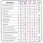
Spotting Burn Marks And Discoloration
Burn marks and discoloration are telltale signs of overheating or electrical issues. These marks are usually dark brown or black spots on the PCB. Discoloration may indicate a component failure or a short circuit. Pay special attention to areas around power components and connectors.
| Visual Clue | Possible Issue |
|---|---|
| Dark brown spots | Overheating components |
| Black marks | Electrical short |
| Yellowish discoloration | Component degradation |
Spotting these issues early can prevent further damage and make troubleshooting easier. Be thorough and take your time during the visual inspection. It is the foundation for all other troubleshooting steps.
Credit: www.aesintl.com
Testing Electrical Connections
Testing electrical connections on a PCB board is crucial. It helps ensure the board functions correctly. Faulty connections can cause the entire system to fail. This section will guide you through testing electrical connections. You will learn about using a multimeter and checking for continuity.
Using A Multimeter
A multimeter is an essential tool. It measures voltage, current, and resistance. Set your multimeter to the appropriate mode. For voltage, choose the DC setting. Place the black probe on the ground point. Place the red probe on the point you want to test. The multimeter will display the voltage. Ensure the reading matches the expected value. For resistance, choose the resistance setting. Connect the probes to the two points you want to test. The multimeter will show the resistance. A low value means good connectivity.
Checking For Continuity
Continuity tests help find broken connections. Set your multimeter to continuity mode. Touch the probes together. The multimeter should beep. This confirms it is working. Now, place the probes on two points of the circuit. If the multimeter beeps, there is continuity. This means the connection is intact. No beep indicates a broken connection. Fix any broken connections you find.
Repairing Damaged Traces
Repairing damaged traces on a PCB board is crucial for restoring functionality. Damaged traces can disrupt the flow of electricity, causing the device to malfunction. Using the right techniques can make the repair process efficient and effective.
Soldering Techniques
Soldering is a common method to repair damaged traces. Start by cleaning the damaged area. Remove any burnt or broken pieces of the trace. Apply a thin layer of flux to the trace. Flux helps the solder to adhere properly.
Heat your soldering iron and apply a small amount of solder to the tip. Gently touch the solder to the damaged trace while heating it with the iron. The solder should flow and fill the gap. Avoid using too much solder, as it can create shorts.
After the solder cools, inspect the repair. Make sure there are no gaps or cold joints. Cold joints can cause intermittent problems. If the repair looks good, you can proceed to the next step.
Using Jumper Wires
Jumper wires can also repair damaged traces. Cut a piece of wire that matches the length of the damaged trace. Strip the ends of the wire to expose the metal.
Apply flux to the areas where the wire will connect. Solder one end of the wire to the start of the damaged trace. Ensure the connection is secure.
Then, solder the other end of the wire to the end of the damaged trace. This creates a new path for the current to flow. Check the connections to ensure they are firm. A loose connection can cause the repair to fail.
Using jumper wires is effective for longer or severely damaged traces. It provides a reliable alternative to soldering alone. Always double-check your work to confirm the repair is successful.
Component Testing And Replacement
Troubleshooting PCB boards often involves testing and replacing components. Identifying faulty components and safely replacing them is crucial. This process ensures the PCB functions correctly. Let’s dive into the steps for effective component testing and replacement.
Identifying Faulty Components
First, visually inspect the PCB for any obvious damage. Look for burnt marks, cracked components, or loose connections. Use a multimeter to test the components. Check resistors, capacitors, and diodes for proper values. Compare the readings with the expected values listed in the PCB’s schematic.
If a component shows abnormal values, it might be faulty. Test one component at a time. This approach helps in accurately identifying the problematic part.
Safe Removal And Replacement
Once you identify a faulty component, prepare to remove it. Use a soldering iron to carefully heat the solder joints. Avoid applying too much heat. This can damage the PCB. Use a desoldering pump to remove the melted solder.
Gently lift the component from the board. Be cautious to avoid damaging the surrounding area. Clean the pads with isopropyl alcohol. This ensures a clean surface for the new component.
Place the new component in the correct orientation. Solder it carefully to the board. Double-check the connections to ensure they are secure. Test the PCB again to confirm the issue is resolved.
Dealing With Soldering Issues
Identifying soldering issues on a PCB board ensures smooth operation. Check for cold joints, bridges, and proper solder flow. Use a magnifying glass to spot tiny defects.
Soldering issues are common in PCB board troubleshooting. Poor soldering can lead to various problems. Identifying and fixing these issues ensures proper functionality. Let’s explore some common soldering problems.Cold Solder Joints
Cold solder joints occur due to insufficient heat. They appear dull and grainy. These joints can cause intermittent connections. To fix them, reheat the joint with a soldering iron. Ensure the solder flows smoothly.Bridged Connections
Bridged connections happen when solder connects two adjacent pads. This creates a short circuit. Check for excessive solder between pins. Use a desoldering tool to remove extra solder. Ensure each pin is separate. “`Advanced Troubleshooting Methods
When dealing with complex PCB issues, basic troubleshooting techniques might not be enough. For more intricate problems, advanced troubleshooting methods are essential. These methods provide deeper insights into the PCB’s functionality and help identify subtle issues that might not be visible through simple inspection.
Using An Oscilloscope
An oscilloscope is a powerful tool in PCB troubleshooting. It helps visualize electrical signals, making it easier to spot irregularities. To use an oscilloscope:
- Connect the oscilloscope probe to the test point on the PCB.
- Adjust the time base and voltage settings for a clear signal.
- Compare the waveform on the screen with the expected signal.
Any deviation from the expected waveform indicates a problem. Look for unexpected spikes, drops, or noise in the signal.
Thermal Imaging For Hotspots
Thermal imaging is another effective technique for PCB troubleshooting. It identifies hotspots which may indicate faulty components. To use thermal imaging:
- Power up the PCB and let it run for a while.
- Use a thermal camera to capture the thermal image of the PCB.
- Analyze the image for unusual heat patterns.
Hotspots often point to components that are overheating. This could be due to excessive current or a failing part. By pinpointing these areas, you can focus your repair efforts effectively.
Preventive Measures
Troubleshooting PCB boards can be complex. Taking preventive measures ensures a longer lifespan and reduces the need for repairs. Simple steps can make a big difference. Here are some key preventive measures to keep in mind.
Proper Handling And Storage
Proper handling and storage of PCB boards are crucial. Always use anti-static wristbands to prevent electrostatic discharge (ESD). ESD can damage sensitive components. Handle boards by their edges, avoiding contact with components and circuits.
Store PCB boards in anti-static bags. Keep them in a dry and cool place. Excess moisture can lead to corrosion, while heat can warp the board. Use desiccants in storage areas to control humidity.
Regular Maintenance Tips
Regular maintenance keeps PCB boards in good condition. Inspect boards for physical damage or burnt components. Use a magnifying glass for a closer look at solder joints and traces.
Clean PCB boards periodically. Dust and debris can cause short circuits. Use a soft brush and isopropyl alcohol for cleaning. Avoid using water or harsh chemicals.
| Task | Frequency | Tools |
|---|---|---|
| Visual Inspection | Monthly | Magnifying Glass |
| Cleaning | Quarterly | Soft Brush, Isopropyl Alcohol |
| Check Connections | Monthly | Multimeter |
Check connections and solder joints regularly. Loose connections can cause intermittent issues. Use a multimeter to test for continuity and proper voltage levels.
Document all maintenance activities. Keep a log of inspections, cleanings, and repairs. This helps in tracking the health of PCB boards over time.
Conclusion And Best Practices
Effective PCB board troubleshooting involves thorough inspection, testing components, and verifying connections. Always use proper tools and follow safety guidelines. Regularly update your knowledge on the latest troubleshooting techniques.
In this section, we summarize the key points of PCB board troubleshooting. We also provide expert advice for future troubleshooting. This ensures you can handle PCB issues effectively.Summary Of Key Points
First, always start with a visual inspection. Look for obvious signs of damage. Burn marks, broken parts, and loose connections are common. Next, use a multimeter to check for continuity. This helps find open or short circuits.Then, test individual components. Capacitors, resistors, and transistors are critical. Replace any faulty parts. Also, check for proper voltage levels. Incorrect voltage often causes malfunction.Finally, clean the PCB. Dust and dirt can cause issues. Use isopropyl alcohol and a brush. A clean board performs better.Expert Advice For Future Troubleshooting
Document your steps. Keep notes on what you check and what you find. This helps track progress and pinpoint issues. Use good tools. High-quality multimeters and oscilloscopes make a big difference. They provide accurate readings.Stay organized. Keep your workspace tidy. Label components and wires. This prevents mistakes. Learn from others. Join forums or groups. Experienced technicians can offer valuable tips. Keep learning. Technology evolves. Stay updated on new PCB designs and troubleshooting techniques.Regular maintenance is essential. Inspect and clean your boards periodically. This prevents many problems. Follow these best practices. They improve your PCB troubleshooting skills. “`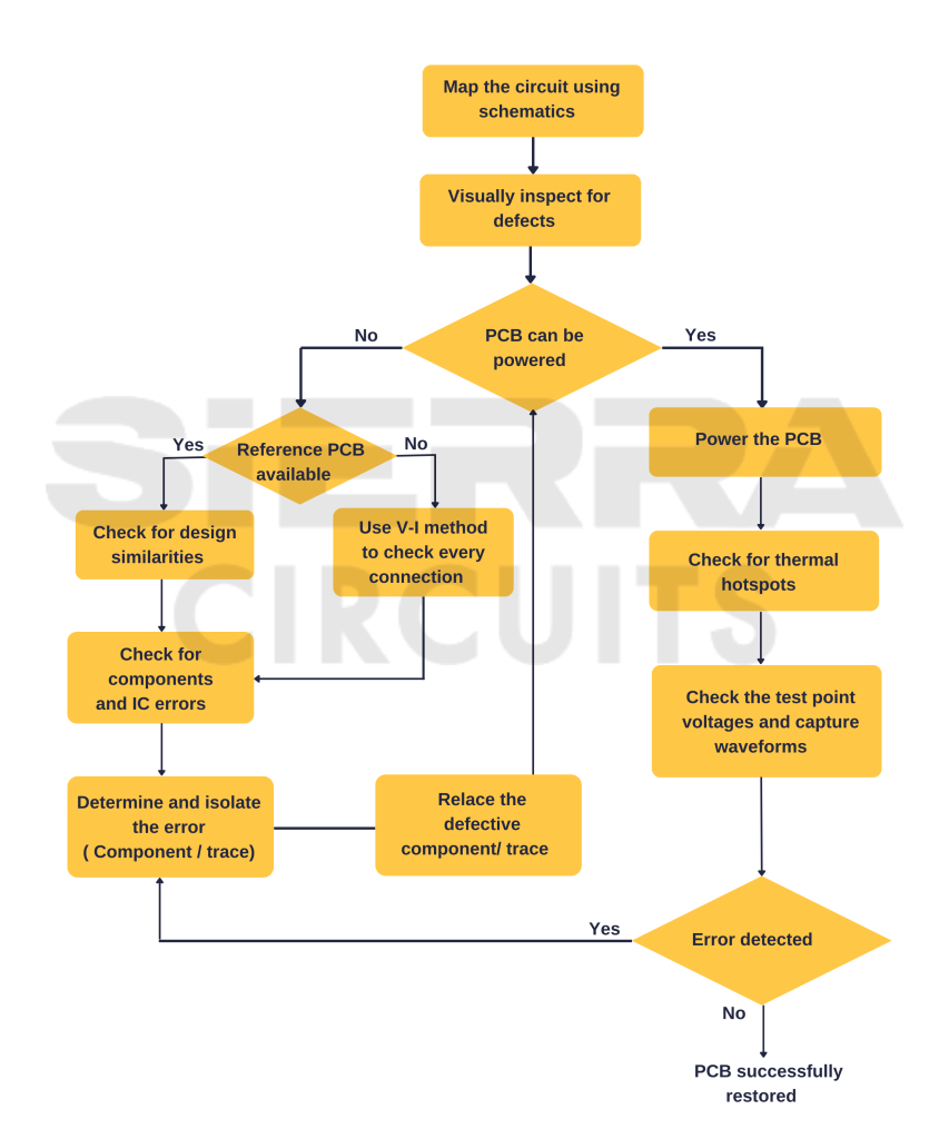
Credit: www.protoexpress.com
Frequently Asked Questions
What Are Common Pcb Board Issues?
Common issues include faulty components, broken traces, and soldering problems. These can cause malfunctions in the circuit.
How Do You Test A Pcb Board?
Use a multimeter to check for continuity. Look for broken connections and faulty components.
What Tools Are Needed For Pcb Troubleshooting?
Essential tools include a multimeter, oscilloscope, soldering iron, and magnifying glass. These help identify and fix issues.
How Can I Identify A Short Circuit On A Pcb?
Check for unexpected continuity between power and ground. Use a multimeter to find the short circuit location.
What Causes A Pcb To Fail?
Failures can be due to manufacturing defects, overheating, and physical damage. Poor design can also lead to failures.
Conclusion
Troubleshooting a PCB board can seem challenging, but it’s manageable. Start with visual checks. Look for obvious signs of damage. Use a multimeter to test connections. Follow the signals step-by-step. Identify and replace faulty components. Patience and practice will improve your skills.
Remember, careful analysis leads to solutions. Always stay safe and work methodically. With these tips, you can effectively troubleshoot PCB boards. Happy repairing!
")