When your PLC system isn’t working as it should, it can bring your entire operation to a halt. You might feel overwhelmed, unsure where to start or what to look for.
That’s where effective PLC troubleshooting becomes your best tool. By understanding the common problems and knowing the right steps to diagnose and fix them, you can save time, reduce downtime, and keep your processes running smoothly. You’ll discover clear, easy-to-follow tips to identify issues quickly and get your PLC back on track without the headache.
Ready to take control of your PLC troubleshooting? Let’s dive in and make your system work for you again.

Credit: www.youtube.com
Plc Components
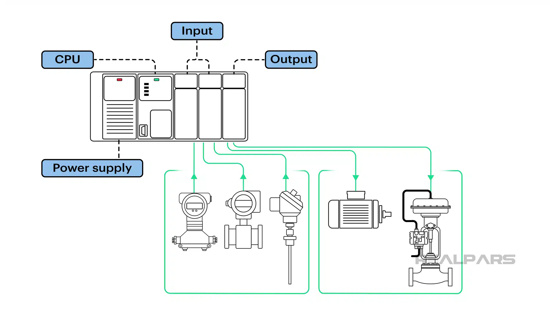
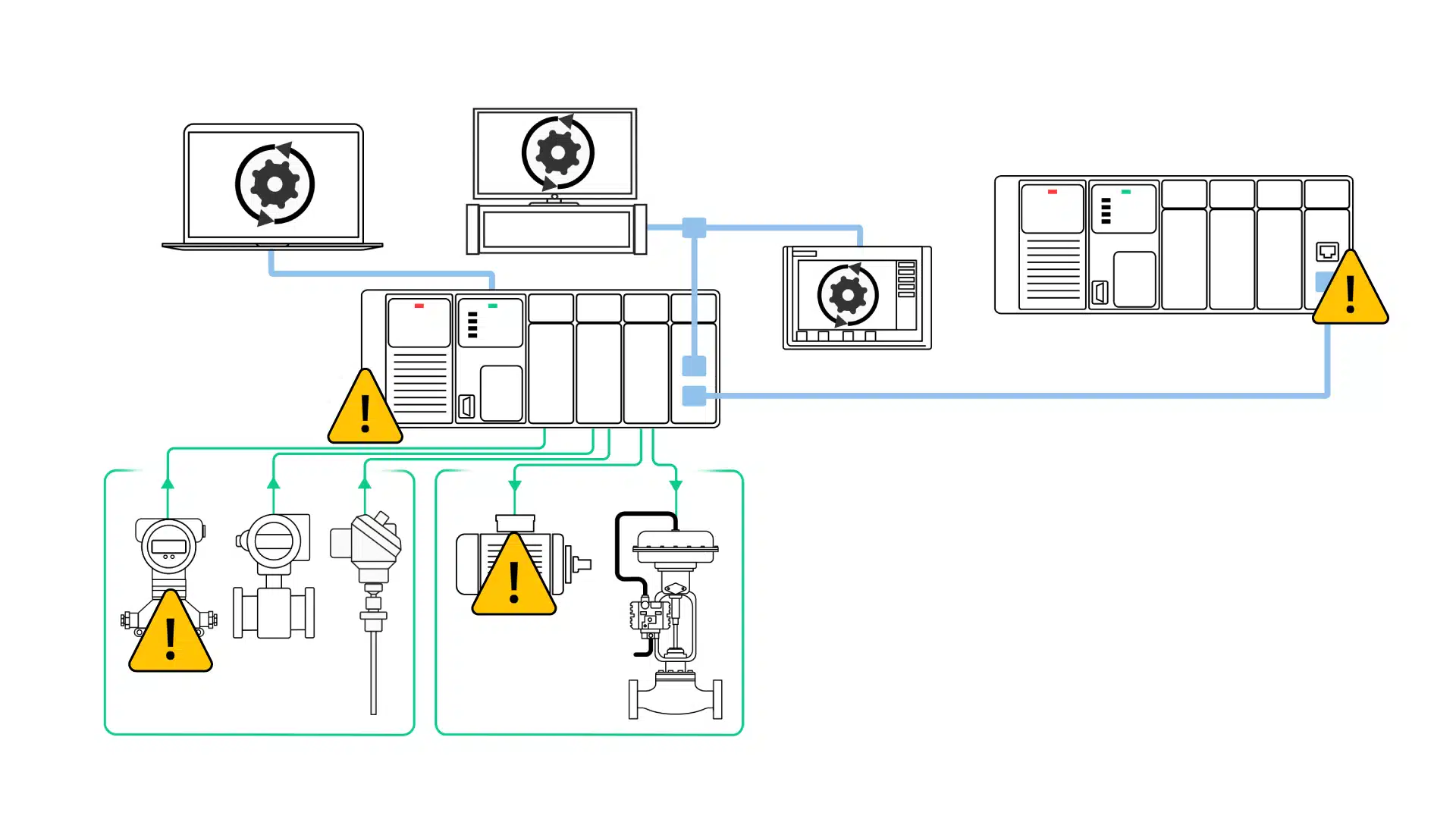
A Programmable Logic Controller (PLC) relies on several key components to operate efficiently. Each part plays a unique role in processing data, powering the system, and communicating with devices.
Understanding these components helps in troubleshooting and maintaining the PLC system. Below is an overview of the main PLC components and their functions.
Cpu Functions
The CPU is the brain of the PLC. It executes the control program and processes input signals. It makes decisions based on the logic written by the programmer. The CPU also manages communication with other parts of the PLC.
Power Supply Role
The power supply provides the necessary voltage to the PLC components. It converts AC voltage to stable DC voltage. Without a reliable power supply, the PLC cannot function properly. It protects the system from voltage spikes and fluctuations.
Input Modules
Input modules receive signals from sensors and switches. They convert physical signals into digital data for the CPU. These modules detect changes in the field devices. They ensure accurate and timely data transfer to the CPU.
Output Modules
Output modules send commands from the CPU to actuators and machines. They convert digital signals into physical actions. These modules control motors, lights, and valves. Proper output module function is vital for system control and safety.
Common Plc Issues
Programmable Logic Controllers (PLCs) are essential in automating machines and processes. Yet, they can face several common issues that disrupt operations. Understanding these problems helps in quick diagnosis and repair. Below are some frequent PLC troubles and their basic causes.
I/o Module Failures
I/O modules connect PLCs to sensors and actuators. Failures occur due to wiring errors, loose connections, or damaged components. Faulty I/O modules cause incorrect data readings or no response from devices. Testing each input and output can identify the faulty module.
Electrical Noise
Electrical noise is unwanted interference from motors, relays, or nearby equipment. It disturbs the PLC signals and causes erratic behavior. Shielded cables and proper grounding reduce noise effects. Avoid running signal cables near power lines to prevent interference.
Memory Corruption
Memory corruption happens when the PLC program or data is damaged. It results from power surges, firmware bugs, or hardware faults. Backing up programs regularly ensures quick recovery. Resetting the PLC and reloading the program often fixes the issue.
Power Supply Problems
PLCs need a stable power supply to function. Fluctuations or failures in power cause unexpected shutdowns or restarts. Check voltage levels and replace faulty power supplies. Using uninterruptible power supplies (UPS) protects against sudden power loss.
Communication Errors
Communication errors occur during data exchange between PLCs and other devices. These errors arise from incorrect settings, cable faults, or network issues. Verify communication parameters and inspect cables for damage. Restarting devices sometimes restores proper communication.
Initial Checks
Before diving deeper into PLC troubleshooting, it is vital to perform initial checks. These checks help identify simple issues that can cause system failure. They save time and prevent unnecessary repairs. Start with the basics to ensure the PLC is ready for further testing.
Power Verification
Check if the PLC power supply is on and stable. Use a multimeter to measure the voltage at the power terminals. Verify the voltage matches the PLC specifications. Look for blown fuses or tripped circuit breakers. A faulty power supply can cause the PLC to stop working or behave erratically.
Cpu Status Lights
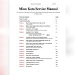
Observe the CPU status LEDs on the PLC. These lights indicate the health of the processor and system errors. A steady green light usually means normal operation. Blinking or red lights may signal faults or communication problems. Consult the PLC manual to interpret the LED codes accurately.
Wiring Inspection
Inspect all wiring connected to the PLC inputs and outputs. Look for loose, damaged, or corroded wires. Ensure connectors are properly seated and terminals are tight. Poor wiring can cause intermittent faults or no signal transmission. Correct wiring issues before moving to advanced diagnostics.
Credit: www.realpars.com
Troubleshooting Steps
Troubleshooting a PLC system requires a clear and methodical approach. Following specific steps helps identify the root cause of the issue quickly. Each step focuses on a critical part of the PLC operation. This approach reduces downtime and ensures smooth system performance.
Input Confirmation
Start by checking all input devices connected to the PLC. Verify sensors, switches, and other inputs send correct signals. Use the PLC’s monitoring tools to see if the inputs register properly. Faulty or loose connections often cause input errors.
Logic Verification
Review the PLC program logic next. Check if the program runs as expected and follows the desired control sequence. Use simulation or debugging features to spot logic errors. Incorrect or missing instructions can disrupt the whole process.
Address And Mapping
Ensure all input and output addresses match the hardware configuration. Address errors lead to wrong data processing and control actions. Cross-check wiring diagrams and program addresses carefully. Proper mapping is crucial for accurate signal flow.
Force Testing
Use force testing to manually override inputs or outputs. This helps isolate faults by simulating signals inside the PLC. Force testing confirms if the PLC hardware and software respond correctly. Avoid leaving forces active after testing to prevent system faults.
Output And Wiring Check
Inspect all output devices and their wiring thoroughly. Look for damaged cables, loose terminals, or burnt components. Test output modules with a multimeter or test lamp. Proper output function is essential for machine operation.
Grounding Check
Check the PLC system’s grounding and electrical connections. Poor grounding causes noise and erratic behavior. Use a tester to verify grounding resistance meets standards. Correct grounding improves system reliability and safety.
Using Software Tools
Using software tools in PLC troubleshooting makes the process faster and more accurate. These tools help technicians see what is happening inside the PLC without opening the device. Software provides a clear view of inputs and outputs, program flow, and errors.
With software, problems can be found and fixed before they cause bigger issues. Many software tools come with easy-to-use interfaces that show real-time data. This helps in understanding how the PLC interacts with the machinery it controls.
Monitoring I/o Signals
Monitoring input and output (I/O) signals is vital during PLC troubleshooting. Software tools show the status of each I/O point clearly. This helps detect whether sensors or actuators work correctly.
Technicians can watch signals change in real time. They see which inputs are active and which outputs respond. This method quickly finds broken wires or faulty devices. It also checks if the PLC logic sends the right commands.
Signal Tracing Techniques
Signal tracing tracks the path of signals through the PLC program. Software tools highlight the flow of signals step by step. This reveals where signals stop or behave unexpectedly.
Tracing helps identify errors in the logic or hardware faults. It shows how inputs lead to outputs through the program’s instructions. By following signals, technicians find the root cause of a problem fast.
These techniques reduce guesswork and save time during repairs. They also improve understanding of the PLC system’s operation.
Credit: www.realpars.com
Preventive Measures
Preventive measures are key to reducing PLC troubleshooting issues. Taking steps early helps avoid costly downtime. Regular care keeps the system running smoothly and extends its life.
Simple actions prevent many common faults. Regular checks catch problems before they grow. This section explains crucial preventive tips for PLC systems.
Avoiding Common Errors
Many PLC errors stem from wiring mistakes. Always double-check connections for correct placement. Use clear labeling to prevent confusion during installation.
Ensure power supply voltage matches PLC requirements. Avoid overloading input and output modules. Keep wiring neat to reduce electrical noise interference.
Use proper grounding to prevent signal disruptions. Update software and firmware regularly to fix bugs. Backup programs frequently to avoid data loss.
Routine Maintenance Tips
Schedule regular inspections of all PLC components. Clean dust and debris from hardware to prevent overheating. Check connectors for corrosion or loose contacts.
Test input and output signals to confirm proper function. Monitor system logs for unusual activity or errors. Replace worn or damaged parts immediately.
Verify battery health in memory retention modules. Perform periodic system resets to clear temporary faults. Train staff to recognize early signs of trouble.
Frequently Asked Questions
What Are The Most Common Defects Of Plc?
Common PLC defects include I/O module failures, electrical noise interference, corrupted memory, power supply issues, and communication errors.
What Are The 5 Basic Operations Of A Plc Controller?
The 5 basic PLC operations are: input scan, program execution, output scan, housekeeping, and communication. These run sequentially in a continuous scan cycle.
What Is The Plc Troubleshooting Checklist?
The PLC troubleshooting checklist includes input confirmation, logic check, address and mapping verification, force testing, output module and wiring inspection, and power supply and grounding checks. These steps help identify and resolve common PLC faults efficiently.
What Are The 4 Main Parts Of Plc?
The four main parts of a PLC are the CPU, Power Supply, Input Modules, and Output Modules. The CPU processes logic, the Power Supply powers the system, Input Modules receive signals from devices, and Output Modules send control signals to external equipment.
What Are Common Causes Of Plc Failures?
Common causes include power supply issues, faulty input/output modules, and electrical noise. Corrupted memory and communication errors also cause failures.
Conclusion
Effective PLC troubleshooting saves time and reduces downtime. Start by checking power and connections first. Test input and output modules carefully. Follow a clear step-by-step process to spot errors. Keep your PLC program logic simple and organized. Regular maintenance helps prevent common faults.
Understanding basic PLC components improves problem-solving skills. Practice these tips to handle issues with confidence. Troubleshooting becomes easier with experience and patience. Stay calm and methodical during each diagnosis. Reliable PLC operation supports smooth industrial processes.
")