When you find yourself staring at a blank display or a flashing alarm light on your refrigeration equipment, performing effective dixell controller troubleshooting is the most reliable way to restore system stability. These digital controllers are widely used in commercial refrigeration for their precision, but they’re also highly sensitive to electrical fluctuations, sensor failures, and parameter corruption. Understanding how to interpret error codes and navigate the menu structure allows you to identify whether the issue is a simple configuration error or a hardware failure requiring a component replacement.
Key Takeaways
- Check the physical integrity of the probe wiring before assuming the controller has failed.
- Most error codes are displayed as a two-letter prefix followed by a numerical value.
- Hard resets can sometimes clear memory glitches, but always back up your parameters first.
- Voltage stability is critical; ensure the power supply matches the controller’s rated input.
- Consult the specific manual for your model, as parameter maps differ between series.
Safety: Inside a mains-powered machine, the parts behind the outer cover can hold a dangerous electrical charge even after it has been unplugged — that’s why they sit behind a cover. Opening the housing, or testing or replacing anything behind it, is a job for a qualified technician, never a home repair.
Troubleshooting Common Dixell Error Codes
The most frequent reason for a technician to initiate a diagnostic sequence is the appearance of an alarm code on the LED screen. These codes serve as the primary diagnostic tool for the device. When the controller detects an anomaly, it pauses normal operation to protect the compressor or the integrity of the stored goods.
| Alarm Code | Meaning | Likely Cause |
|---|---|---|
| P1 | Room Probe Failure | Disconnected or faulty probe |
| P2 | Evaporator Probe Failure | Damaged sensor or broken wire |
| HA | High Temperature Alarm | Compressor failure or door left open |
| LA | Low Temperature Alarm | Thermostat set too low or sensor drift |
| EA | External Alarm | Triggered by a secondary safety switch |
How to Access Hidden Parameters
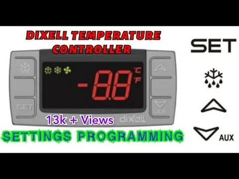
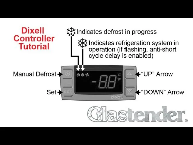
Often, the controller is functioning correctly, but the setpoints have been modified, causing the system to short-cycle or fail to pull down to the desired temperature. To change these, you must enter the programming menu. This is usually done by holding the “Set” and “Down” buttons simultaneously for several seconds until the label “Pr1” appears.
Parameter security levels are often enabled by manufacturers to prevent unauthorized changes. If you can’t modify a value, you may need to enter a password, which is typically set to “321” on many default factory configurations. Once inside, you can navigate the list using the arrow keys. Always document the original value before making any adjustments to ensure you can revert the system to its previous state if the change doesn’t resolve the issue.
Diagnosing Compressor Start Issues
If your compressor isn’t starting, the controller might be stuck in a defrost cycle or a safety delay period. The controller is programmed to prevent the compressor from cycling too rapidly to avoid motor burnout. Check if the “Defrost” icon is illuminated on the display. If it is, the controller is currently in a heating cycle to melt ice buildup on the evaporator coils.
- Check the “AC” (Anti-Cycle) parameter, which dictates the minimum time between compressor starts.
- Verify the “COn” and “COF” parameters, which represent the compressor on and off times during a probe failure.
- Ensure the digital input (DI) isn’t configured to a “standby” mode that prevents the output relay from closing.
Pro Tip: Always verify that the relay output is actually receiving voltage at the terminal before condemning the controller itself. If the controller display shows the compressor should be “On” but there’s no voltage at the output terminal, the internal relay has likely failed due to an inductive load surge.
Identifying Power Supply Problems
Electronic controllers are highly susceptible to voltage spikes. If the display is flickering, blank, or showing nonsensical characters, the power supply is the first suspect. Most Dixell units operate on 12V, 24V, or 110V/230V depending on the specific model. A technical guide for refrigeration controllers provides the specific electrical requirements for each series, as using the wrong voltage will permanently damage the internal transformer.
When checking the power, look for corroded terminal connections. Humidity in refrigeration environments often leads to oxidation, which increases resistance and causes intermittent power drops. Use a fine wire brush to clean the spade connectors and ensure they’re tight. If the screen remains blank after confirming the correct input voltage, the internal capacitor or power module has likely reached the end of its service life.
Why is My Display Flashing?
A flashing display is the universal sign of an active alarm state. It isn’t necessarily a sign that the controller is broken; rather, it’s a sign that the controller is doing exactly what it was programmed to do—alerting you to a breach of the set temperature limits.
The most common cause for a persistent flashing display is a high-temperature alarm (HA). This happens when the temperature inside the cabinet exceeds the “ALU” (Alarm Upper) parameter for longer than the “ALd” (Alarm Delay) time. This is often caused by:
- Excessive door openings during restocking.
- A failed condenser fan motor causing high head pressure.
- A clogged condenser coil that prevents heat rejection.
- A low refrigerant charge leading to poor cooling capacity.
Performing a Factory Reset
If you have exhausted all other troubleshooting steps and the controller is behaving erratically, you may need to perform a factory reset. This clears all user-defined parameters and restores the original settings.
Warning: Performing a reset will wipe all custom configurations, including defrost schedules, alarm setpoints, and communication addresses. Ensure you have the original parameter sheet provided by the equipment manufacturer before proceeding, as the default factory settings may not be suitable for your specific cooling application.
To reset the device, you usually hold the “Set” and “Up” buttons during the power-on sequence. This will often prompt a “rSt” message on the display. Once the reset is complete, you must manually re-enter the configuration parameters to match the requirements of your refrigeration system.
Troubleshooting Communication Errors
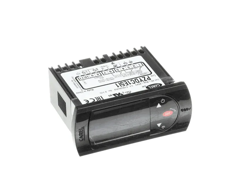
If your controller is part of a larger monitoring network (such as a Modbus system), you might encounter communication errors. These are typically displayed as “noL” or specific serial numbers on the screen. The issue is rarely the controller itself; it’s usually a broken data cable or a mismatch in the baud rate settings between the controller and the master computer.
Check the following to resolve communication issues:
- Ensure the “Adr” (Address) parameter is unique for every controller on the loop.
- Verify the polarity of the data wires; swapping the positive and negative leads will prevent data transmission.
- Check for “daisy-chain” wiring errors where the end-of-line resistor is missing or improperly installed.
Frequently Asked Questions
Why does my controller show a P1 error?
A P1 error indicates that the room temperature probe is either disconnected, shorted, or open. This prevents the controller from knowing the current cabinet temperature, so it defaults to a safety mode. You should inspect the sensor wire for cuts or corrosion. If the wiring is intact, the probe itself has likely failed and requires a replacement to restore normal operation.
Can I replace a probe while the unit is running?
Yes, you can replace a probe while the unit is powered, but it’s safer to turn the power off to avoid a short circuit. If you replace it while live, the controller will register the new resistance value immediately. Ensure the new probe is the same type, such as an NTC or PTC, as these aren’t interchangeable without changing the internal controller settings.
What does the “dEF” message mean?
The “dEF” message on the display indicates that the controller is currently running a defrost cycle. This is a normal function of the unit, designed to melt frost from the evaporator coils. If the unit stays in this mode for hours, there may be an issue with the defrost termination probe or the defrost timer settings within the parameter menu.
How do I know if the relay is bad?
If the controller display indicates that a function, such as the compressor or lights, should be active, but the component doesn’t turn on, the internal relay is the likely culprit. You can verify this by checking for voltage at the output terminal. If the controller shows the status as “On” but there’s no output voltage, the relay contacts have failed.
How often should I calibrate the probe?
Calibration isn’t typically required unless you notice a consistent drift between the displayed temperature and a handheld thermometer. If you observe a steady offset, you can adjust the “Ot” (Offset) parameter in the menu. This allows you to calibrate the controller to match the actual temperature inside the cabinet without needing to replace the sensor hardware.
Conclusion
Maintaining your cooling equipment requires consistent attention to these electronic signals. If you have confirmed the power supply is stable, the probes are reading correctly, and the relays are engaging, yet the system still fails to cool, the issue likely resides in the mechanical refrigeration circuit rather than the controller. Consult your equipment’s service manual to verify that your current parameter set matches the factory specifications for your specific load requirements.